
From the name itself, a block diagram is an illustration that portrays the fundamental parts of a system whose key processes are represented by blocks. Another component that makes up this diagram is line to show the relationship and connect between subsequent blocks. Furthermore, this is regarded as a high-level flowchart that allows engineers to describe details in hardware design the simplest way possible. To fully understand and learn how to draw a block diagram, we will discuss everything you need to know below.
DOWNLOADDefinition of Block Diagram
A block diagram is a typical visual representation of a system that displays the input and output through blocks joined by lines. It’s purpose though does not have any concern about the process from the input and how to get to output. In other words, what happens in between is not important. The focus of this diagram is for engineers to easily identify or quickly point out spots that may cause trouble.
Another key thing to remember, it is a specialized diagram that will help you create a structure of a complicated workflow or algorithms in a precise illustration. This way, you will have a clear picture where all the major parts of a system are located. Also, you may use it to define the specific parts of the software. That being said, it is a great tool to assist engineers, hardware, and software developers to design or update existing systems.
Basic Components of Block Diagram
Drawing a system block diagram is relatively easy. You just have to be familiar with the components of what makes up this diagram. It only consists of basic geometric shapes and symbols. Below are their functions and uses.
Box– represents the major part or function in a system. Every block in a system has only one input and output.
Line– this symbol connects the boxes in a system to illustrate relationships.
Arrow Line– this figure is specifically used to indicate the flow of the signal or data through the electrical block diagram and software design.
Note: Other details may be necessary to help readers clearly analyze the system. This is true for most electrical diagram analysis which requires additional schematic symbols when showing particular properties.
Block Diagram Uses and Examples by GitMind
In engineering, this is a useful diagram to depict principal parts and functional processes in different fields. Drawing this diagram does not need any technical knowledge. But the best method to study and understand is by looking at some examples. You may choose from the diagrams below and edit them.
Functional block diagram
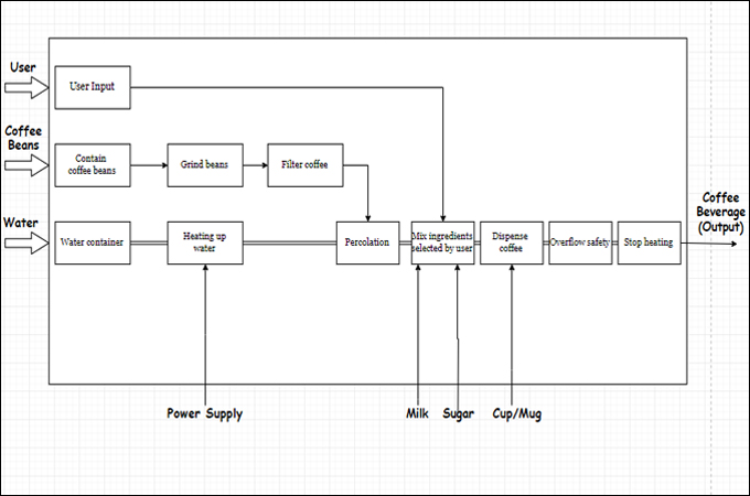
This diagram is an example of a functional block diagram that demonstrates the process of automatic coffee machines. Upon looking at the diagram, we can identify the main functions of the system. This includes user preference input, grinding coffee beans, and heating up the water.
System block diagram
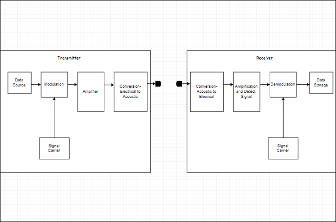
When there are too many key properties in a single system, a block diagram is an effective tool to decipher and complete the articulation of different processes. This principle is referred to as a system block diagram. This makes the diagram more manageable. Just like the example below where there are two separate systems that work simultaneously. For this matter, a diagram of a projector and hydrophone is the best example.
Control block diagram
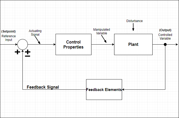
This figure depicts the feedback control system. It shows the processes of the feedback system through a block diagram. Also, this is helpful to demonstrate the flow paths control signals. However, don’t be mislead by the thinking that it depicts the process of energy flowing through the system.
Electrical block diagram
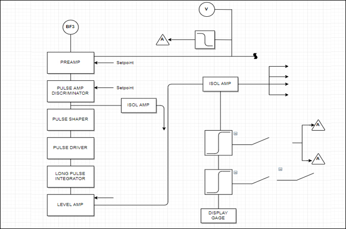
You can also create an electrical block diagram to draw the wiring or circuit of a hardware system. On the other hand, the diagram exhibits the measurement for neutron flux and generate output signals. As shown in the illustration, it shows several blocks of different sizes that translate to multiple functions in key properties.
Conclusion
Whether you are a beginner or an advanced user, you can create your block diagram and apply them to any engineering fields. All you need is basic knowledge to start creating your first or next diagram. You can also click one of these diagrams and edit them for free.
Leave a Comment